I have a Schwinn 213 Recumbent Exercise Bike and it came with a hand-grip style heart rate monitor (HRM). Unfortunately HRM died couple of years ago just after the warranty is ended. I did not like the hand-grip HRM from the beginning as it was inaccurate and required me to hold the hand-grips all the time.
I’ve been playing with Polar heart rate (HR) receiver for a while and it is really easy to use. So, I decided to open up the recumbent bike’s console and replace the hand-grip HRM system with the Polar HRM system.
Let’s start with the Polar RMCM01 HR receiver unit. All you need is 3 additional components to make it work; couple of 1Kohm resistors and a 32.768 kHz, 12.5pF load capacitance crystal. Follow page 7 on the datasheet to get together your Polar HRM device or see below.

Here is the Datasheet. (I can no longer find any stand-alone RMCM01 units for purchase. SparkFun stopped selling stand-alone units for some reason, they only have it mounted on an interface board.)
Once you build your sensor, you can hook it up to 3V DC, put your chest strap on and test it with an oscilloscope. The unit sends 1ms pulse of 3V every time it detects a heart rate. Here is an example output form the unit when it receives the HR.

As you can see, the frequency of the signal is 1.359 Hz. You can calculate the HR with a simple calculation: 1.359 * 60 = 81.54. So the HR is about 81 beats per minute (BPM).
How to hack the bike’s computer:
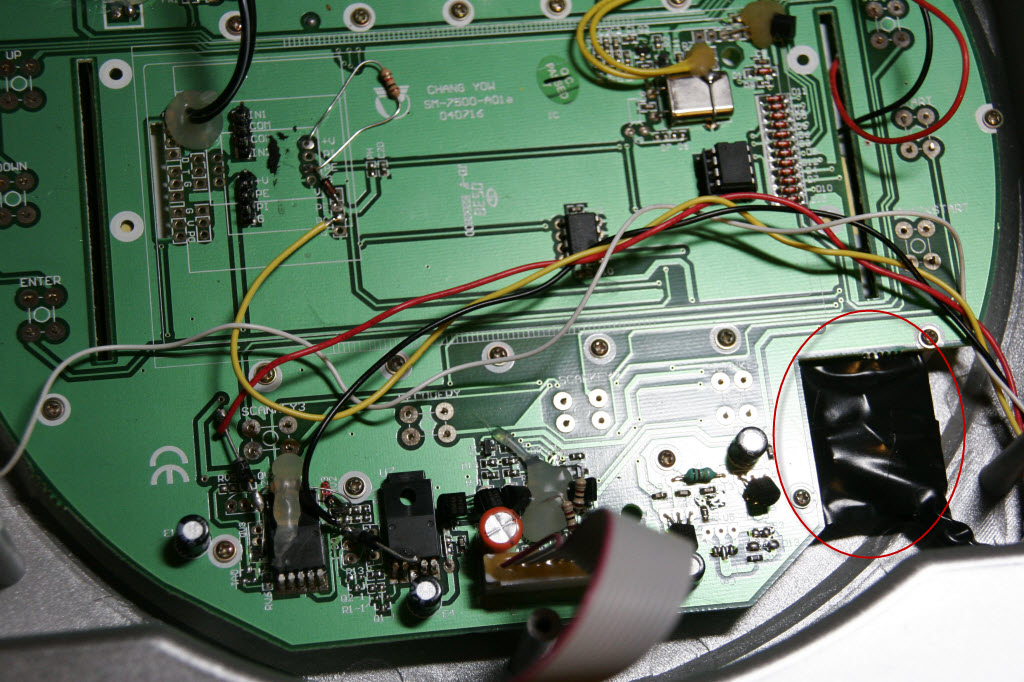
Unfortunately I forgot to take a picture of the board before I removed the hand-grip HRM unit and made modifications, so I’ll try to illustrate the original condition on the modified board.

The black block in the picture is where I found the original hand-grip HRM unit. It looks like this:
 |
 |
As you can see it is pretty much a black-box. If I wanted to fix it, I had to remove all that epoxy or resin they used to protect the unit, too laborious for me to tackle. It, however, gave clues as to how it was working. When you look at the board you see ports marked L and R, this is simply for the hand-grips and there is nothing interesting there. What I have left with V+, G, P0 and P1. V+ and G are obvious. So the business end of this unit is P0 and P1. Since the unit was not working, I had no idea what type of signal it generated. When I tested the console without the HRM unit installed it did not show the little heart symbol on the screen indicating that it wasn’t receiving a HR. When I installed the HRM unit back on, the little heart symbol was erratically blinking, indicating that the HR was present but couldn’t calculate what it was.
So, I hooked up my oscilloscope to the P0 and P1 lines to see what was going on. The P0 and P1 was low when the unit was off. When I turned the unit on, both P0 and P1 was going high and staying high. I un-hooked the P1 to see what the little heart console indicator showed. Surprisingly it showed HR detected. When I un-hooked the P0 and hooked P1 back on, the indicator showed no HR detected. So HR detection is controlled by P0. When P0 is high HR is present, when it is low HR is not present. Great!
I needed to figure out how P1 was sending the heart signal. At this point I assumed the fact that the P1 line is sending some kind of a square wave indicating the HR. I grabbed my signal generator, set it up to the same amplitude the circuit was running on (4V) and generated 1 Hz square-wave signal. I started the console, pulled P0 to high and fed 1 HZ square-wave signal to the P1. Several seconds later the console on the bike displayed a heart rate: 60 BPM. Bingo!
Square-wave I generated was symmetrical, but the Polar unit generates 1ms pulse, can the microcontroller on the bike’s console read the 1ms pulse signals? I just had to try and see. I hooked the Polar HRM unit’s HR output the bike’s P1 input. Several seconds later, my heart rate was shown on the console. *grin* That was easy.
Now, I had to make my modifications on the console board and find a 3V power source for the Polar HRM unit. Here is what I did:
I found couple of BA033ST 3.3V voltage regulators on the console’s board. I decided to hook the Polar HRM unit to one of them. However the output of these voltage regulators were hovering around 3.4V, which is the maximum voltage Polar unit can accept. To be on the safe side I wanted to use a voltage below 3.4V, so I decided to add a 1N4001 diode to the voltage regulator’s output to drop the voltage. Since the 1N4001 have a forward voltage drop of 0.7V, it pulled the voltage down to a safer range for the Polar HRM unit. See below:
 This is before I modified the board.
 After the modification.
Now I had to permanently pull P0 to high. This was relatively easy as all I had to do is to add 10 KOhm resistor to the V+ (4V) coming out of the board and connect it to P0 (Marked PE on the console board). It would’ve been better if I used FPLS output from the Polar receiver, but I neglected to hook a wire for that output so I used this method instead.
 Before the modification.
 After the modification.
Now the hookup is complete, I had to find a nice cozy place for the Polar HRM unit. Luckily right bottom of the console there was a perfect place for it.

All done. Here is a video that shows how the unit functions now:
This rocks! What a clever hack. Thanks Levent.
Thanks Rick. 🙂